The Future of Gear Manufacturing: Innovations and Trends You Need to Know
Introduction
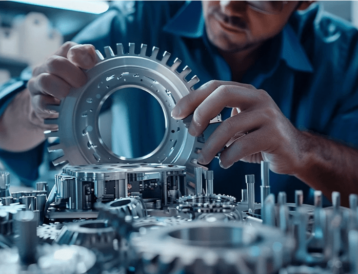
The manufacturing of gears is equally important in industrial fields such as automobiles, aircraft, robotics, etc. which captions the advancement and accuracy. Modern techniques and a variety of superior materials are in the process of changing more traditionally made gears through technological improvement.
And that’s not the end of it – the possibilities are endless as the advancement into automation and additive manufacturing does an about turn into focus on sustainability.
This article looks at some of the latest trends and technologies being adopted by the industry to remain relevant and profitable to manufacturers. It is critical although they are based in various fields such as an engineer, machinist, or businessman to understand these kinds of developments to survive in the ever-changing industry.
Gear Manufacturing Process Definition
The gear manufacturing process includes accurate planning of a number of steps to achieve perfect dimensional accuracy, accurate profile of the gear, and perfect functional accuracy of the gear. This process enables gears to meet the specific requirements in their varied uses including car manufacturing to industrial use.
The common gear manufacturing process flow chart is depicted as follows; raw materials are selected and processed then there is the use of cutting, hobbing, and grinding to produce some gears. Heat treatments help to increase the product’s working resources and resist intensive mechanical wear, and other methods, such as chamfering and deburring, affect the product’s performance.
Last but not least, the high-quality control to make the gears that meet the industry requirement and application necessity.
This system within the gear manufacturing process guarantees reliability, durability, and high accuracy, which are prerequisites for contemporary mechanisms and equipment.
1. Gear Manufacturing Processes details: Gear Designing
Gear designing is a very sensitive phase in the gear manufacturing process which forms the basis for making gears that transmit power satisfactorily and execute mechanical movements accurately.
This phase relies on engineering discipline to match the enhanced technology to the particular functionality to get better reliability and more life for the gear. Key factors in gear design are the software tool, geometry calculation, material selection, and choice which are the vital components in the successful development of the gear.
The Fundamentals of Gear Designing
Gear designing activity therefore involves the decision of the size, form, and operation of gears to be used in a given situation. It makes it possible for the physical gear can bear the required loads, and transmit torque effectively to function as expected under various conditions.
This process is very critical in gears that come into crucial sectors of the market such as automotive, aerospace, as well as industries.
Leveraging Gear Design Software
Computer applications specifically related to gear design form the core of diminishing the challenges and enhancing the standard of the design process. These tools provide engineers with precise simulation and calculation capability to obtain the optimum design and substantially reduced leading time.
- Efficiency: Computer-aided gear design tools make complex calculations of gear strength, its performance, and shape Geometry of the teeth.
- Simulation: One is that it helps in undertaking virtual tests applied to gears to confirm that in particular loads or conditions, the gears will function as expected.
- Optimization: Software helps in reducing risks and improving the outcome of the product since it flags design errors when they are being developed.
CAD modeling in gear designing
CAD Modeling is a vital tool in the design of gears since it enables engineers to come up with 3D models of gears with dimensions. It offers several benefits:
- Visualization: Drawing of the gear using CAD enables the engineers to have a perception of the structural formation of the gear and how it relates to other components.
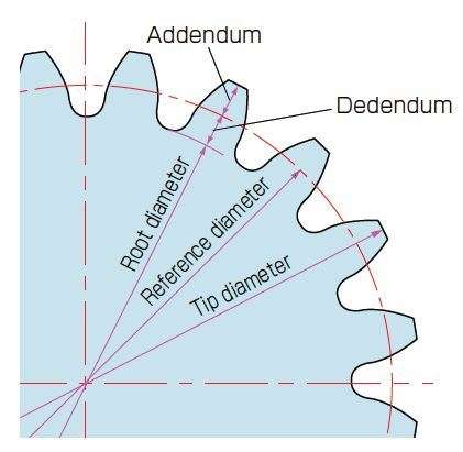
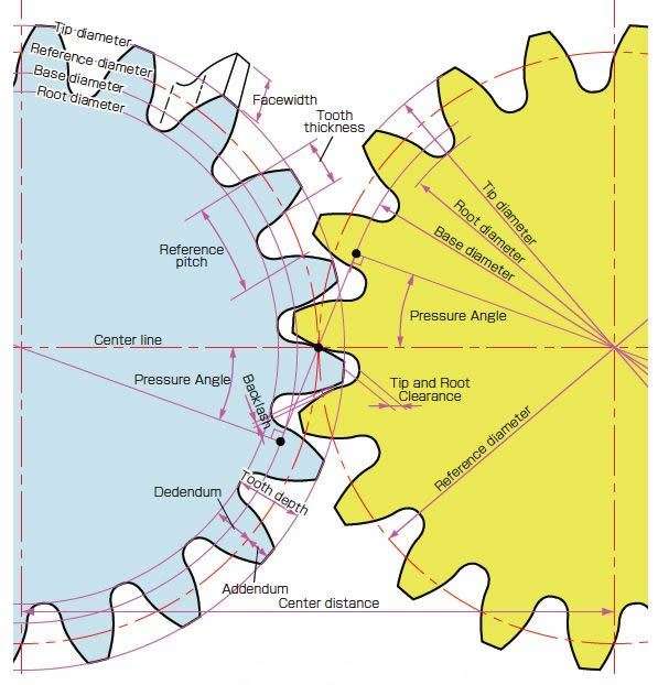
- Customization: Values such as tooth size, pitch diameter, and module are easily changeable to abide by certain standards.
- Accuracy: CAD guarantees a design match to certain special standards and specifications of tolerance, thus lowering the prospects of manufacturing defects.
Module of Gear: Defining Gear Size
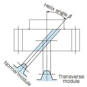
The term module of gear is also among the parameters defined for gear design; it is equal to the ratio of the pitch diameter to the number of gear teeth. It is stated in millimeters and covers the general dimension and pitch of the gear teeth.
- Standardization: Innovations in choosing the correct module are made, hence addressing the issue of compatibility of gears in a given system.
- Performance: The gear module chartinfluences the strength, load-carrying capacity, and surface finish of the gear.
- Application: Small-scale gears are mainly used in applications that require accurate control, while large-scale gears are used in large mechanical equipment.
Optimizing Gear Tooth Profile
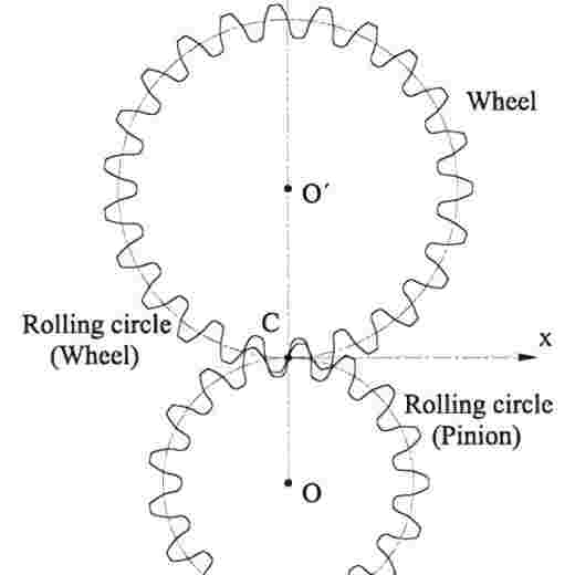
The strength and performance of the gear depend on the gear tooth profile. Despite this, involute profiles are the most used since they enable a delicate transfer of power from the drive to the screw without much wearing away.
- Accuracy: Thickness of the flank and tooth reduces wear and promotes better contact between the two surfaces which thereby provides smothering working of the machine parts.
- Durability: When teeth are well designed, then the gear loadis distributed over a large area hence not straining the machinery.
- Quiet Operation: The engineering design of profiles minimizes the level of noise and vibration within the structure while in operation.
Importance of Gear Teeth and Diametric Pitch
The pressure angle at which the gears will revolve and the relative force via which the torque will be imparted are both described by the number of gear teeth that are provided to a gear.
The geometry of the gear and its performance characteristics are determined by these elements, in addition to the diametric pitch circle, which shows the number of teeth about the diameter of the gear.
- Design: These diametral pitchesare crucial in making verification of the degree of conformity of two mated gears.
- Strength: Since the gear standardis required to withstand operational loads that it has to bear, its geometry has to be set right, to begin with, and aligned teeth are those that can bear these loads without distorting the shape of the gear any further.
The process of creating gears is fairly complicated since it requires theoretical calculations in addition to the assistance of computer-based designs, such as CAD modeling and gear design software.
| Rules and Formulas | |||
| For Spur Gear Calculations | |||
| Diametral Pitch is the number of teeth to each inch of the pitch diameter . | |||
| To Find | Having | Rule | Formula |
| Diametrical Pitch (DP) | Circular Pitch (CP) | Divide 3 .1416 by Circular Pitch (CP) | 3 .1416 DP = CP |
| Pitch Diameter (PD) and Number of Teeth (N) |
Divide Number of Teeth (N) by Pitch Diameter (PD) | DP = | |
| Outside Diameter (OD) and Number of Teeth (N) |
Divide Number of Teeth (N) plus 2 by Outside Diameter (OD) |
DP = N + 2 OD |
|
| Pitch Diameter (PD) | Number of Teeth (N) and Diametral Pitch (DP) |
Divide Number of Teeth (N) by Diametral Pitch (DP) | PD = |
| Number of Teeth (N) and Outside Diameter (OD) |
Divide product of Outside Diameter (OD) and Number of Teeth (N) by Number of Teeth (N) plus 2 |
PD = | |
| Outside Diameter (OD) and Diametral Pitch (DP) |
Subtract from Outside Diameter (OD) quotient of 2 divided by Diametral Pitch (DP) |
PD = OD - (2 ÷ DP) | |
| Addendum (a) and Number of Teeth (N) |
Multiply Addendum (a) by Number of Teeth (N) | PD = a × N | |
| Outside Diameter (OD) | Number of Teeth (N) and Diametral Pitch (DP) |
Divide Number of Teeth (N) plus 2 by Diametral Pitch (DP) |
OD = |
| Pitch Diameter (PD) and Diametral Pitch (DP) |
Add to Pitch Diameter (PD) quotient of 2 divided by Diametral Pitch (DP) |
OD = PD + | |
| Pitch Diameter (PD) and Number of Teeth (N) |
Divide Number of Teeth (N) plus 2 by quotient of Number of Teeth (N) divided by Pitch Diameter (PD) |
OD = | |
| Number of Teeth (N) and Addendum (a) |
Multiply Number of Teeth (N) plus 2 by Addendum (a) | OD = (N + 2) × a | |
| Number Of Teeth (N) | Pitch Diameter (PD) and Diametral Pitch (DP) |
Multiply Pitch Diameter (PD) by Diametral Pitch (DP) | N = PD × DP |
| Outside Diameter (OD) and Diametral Pitch (DP) |
Multiply Outside Diameter (OD) by Diametral Pitch (DP) and subtract 2 |
N = (OD × DP) - 2 | |
| Thickness Of Tooth (t) | Diametral Pitch (DP) | Divide 1 .5708 By Diametral Pitch (DP) | t = |
| Addendum (a) | Diametral Pitch (DP) | Divide 1 by Diametral Pitch (DP) | 1 a = DP |
| Dedendum (b) | Diametral Pitch (DP) | Divide 1 .157 By Diametral Pitch (DP) | b = |
| Working Depth (hk) | Diametral Pitch (DP) | Divide 2 by Diametral Pitch (DP) | hk = |
| Whole Depth (ht) | Diametral Pitch (DP) | Divide 2 .157 By Diametral Pitch (DP) | ht = |
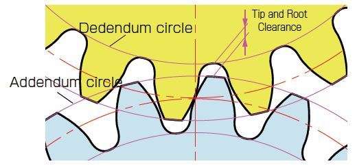
| Clearance (c) | Diametral Pitch (DP) | Divide .157 By Diametral Pitch (DP) | .157 c = DP |
| Thickness of Tooth (t) | Divide Thickness of Tooth (t) at Pitch Line by 10 | t c = 10 |
|
| Note: Rules and formulas relating to tooth depth and outside diameter apply to full-depth, equal addendum gears . | |||
There are some sorts of applications in which a relative characteristic such as the module of gear, gear tooth profile, and diametric pitch is of critical importance as a guarantee of the performance of the gears teeth calculator.
Manufacturing businesses can provide industries with the high-quality gear that they demand as a result of their decision to emphasize precision and the utilization of modern technology.
| Dimensions of Standard Full-depth Teeth | |||||||
| Diametral Pitch | Circular Pitch | Module | Arc thickness of Tooth on Pitch Line |
Addendum | Working Depth of tooth |
Dedendum of Depth of Space Below Pitch Line |
Whole Depth of Tooth* |
| 1/2 | 6.2832 | 50.8 | 3.1416 | 2.0000 | 4.0000 | 2.3142 | 4.3142 |
| 3/4 | 4.1888 | 33.8667 | 2.0944 | 1.3333 | 2.6666 | 1.5428 | 2.8761 |
| 1 | 3.1416 | 25.4 | 1.5708 | 1.0000 | 2.0000 | 1.1571 | 2.1571 |
| 1 1/4 | 2.5133 | 20.32 | 1.2566 | 0.8000 | 1.6000 | 0.9257 | 1.7257 |
| 1 1/2 | 2.0944 | 16.9333 | 1.0472 | 0.6666 | 1.3333 | 0.7714 | 1.4381 |
| 1 3/4 2 2 1/4 2 1/2 2 3/4 |
1 .7952 1 .5708 1 .3963 1 .2566 1 .1424 |
14 .5143 12 .7 11 .2889 10 .16 9 .2364 |
0 .8976 0 .7854 0 .6981 0 .6283 0 .5712 |
0 .5714 0 .5000 0 .4444 0 .4000 0 .3636 |
1 .1429 1 .0000 0 .8888 0 .8000 0 .7273 |
0 .6612 0 .5785 0 .5143 0 .4628 0 .4208 |
1 .2326 1 .0785 0 .9587 0 .8628 0 .7844 |
| 3 | 1.0472 | 8.4667 | 0.5236 | 0.3333 | 0.6666 | 0.3857 | 0.7190 |
| 3 1/2 | 0.8976 | 7.2571 | 0.4488 | 0.2857 | 0.5714 | 0.3306 | 0.6163 |
| 4 | 0.7854 | 6.35 | 0.3927 | 0.2500 | 0.5000 | 0.2893 | 0.5393 |
| 5 | 0.6283 | 5.08 | 0.3142 | 0.2000 | 0.4000 | 0.2314 | 0.4314 |
| 6 | 0.5236 | 4.2333 | 0.2618 | 0.1666 | 0.3333 | 0.1928 | 0.3595 |
| 7 | 0.4488 | 3.6286 | 0.2244 | 0.1429 | 0.2857 | 0.1653 | 0.3081 |
| 8 | 0.3927 | 3.175 | 0.1963 | 0.1250 | 0.2500 | 0.1446 | 0.2696 |
| 9 | 0.3491 | 2.8222 | 0.1745 | 0.1111 | 0.2222 | 0.1286 | 0.2397 |
| 10 | 0.3142 | 2.54 | 0.1571 | 0.1000 | 0.2000 | 0.1157 | 0.2157 |
| 11 | 0.2856 | 2.3091 | 0.1428 | 0.0909 | 0.1818 | 0.1052 | 0.1961 |
| 12 | 0.2618 | 2.1167 | 0.1309 | 0.0833 | 0.1666 | 0.0964 | 0.1798 |
| 13 | 0.2417 | 1.9538 | 0.1208 | 0.0769 | 0.1538 | 0.0890 | 0.1659 |
| 14 | 0.2244 | 1.8143 | 0.1122 | 0.0714 | 0.1429 | 0.0826 | 0.1541 |
| 15 | 0.2094 | 1.6933 | 0.1047 | 0.0666 | 0.1333 | 0.0771 | 0.1438 |
| 16 | 0.1963 | 1.5875 | 0.0982 | 0.0625 | 0.1250 | 0.0723 | 0.1348 |
| 17 | 0.1848 | 1.4941 | 0.0924 | 0.0588 | 0.1176 | 0.0681 | 0.1269 |
| 18 | 0.1745 | 1.4111 | 0.0873 | 0.0555 | 0.1111 | 0.0643 | 0.1198 |
| 19 | 0.1653 | 1.3368 | 0.0827 | 0.0526 | 0.1053 | 0.0609 | 0.1135 |
| 20 | 0.1571 | 1.27 | 0.0785 | 0.0500 | 0.1000 | 0.0579 | 0.1079 |
| 22 | 0.1428 | 1.1545 | 0.0714 | 0.0455 | 0.0909 | 0.0526 | 0.0980 |
| 24 | 0.1309 | 1.0583 | 0.0654 | 0.0417 | 0.0833 | 0.0482 | 0.0898 |
| 26 | 0.1208 | 0.9769 | 0.0604 | 0.0385 | 0.0769 | 0.0445 | 0.0829 |
| 28 | 0.1122 | 0.9071 | 0.0561 | 0.0357 | 0.0714 | 0.0413 | 0.0770 |
| 30 | 0.1047 | 0.8467 | 0.0524 | 0.0333 | 0.0666 | 0.0386 | 0.0719 |
| 32 | 0.0982 | 0.7938 | 0.0491 | 0.0312 | 0.0625 | 0.0362 | 0.0674 |
| 34 | 0.0924 | 0.7471 | 0.0462 | 0.0294 | 0.0588 | 0.0340 | 0.0634 |
| 36 | 0.0873 | 0.7056 | 0.0436 | 0.0278 | 0.0555 | 0.0321 | 0.0599 |
| 38 | 0.0827 | 0.6684 | 0.0413 | 0.0263 | 0.0526 | 0.0304 | 0.0568 |
| 40 | 0.0785 | 0.635 | 0.0393 | 0.0250 | 0.0500 | 0.0289 | 0.0539 |
| *NOTE: Dimensions listed are for HOB CUT TEETH ONLY . Shaper cut teeth may be slightly larger . Consult factory for exact measurement . | |||||||
2.Different gear for different gear applications
Gears form part of the mechanical system and based on use they vary to suit the gear applications in the system. Here’s how different gears serve the automotive industry, aerospace industry, construction industry, energy industry, and medical device industry:
1. Spur Gears
Gear Application:
Power transmission employing the construction described above was quite suitable to couple power between sets of parallel shafts and in many applications, it was operationally simple.
Industries:
- Automotive Industry: Spur Gear used in transmissions and differential drives for precise force communication.
- Energy Industry: Coming up in the power plants as well as the wind turbines for proper and efficient conversion of energy.
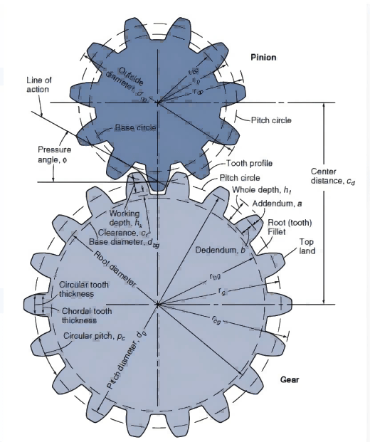
2. Helical Gears
Gear Application:
Helical Gears function with little noise at higher loads due to features of angled teeth.
Industries:
- Aerospace Industry:Indispensable for jet engine and propulsion systems required to work with high-speed capability.
- Construction Industry: Applied in conveyor belts and in equipment where strength and efficiency are a prerequisite.
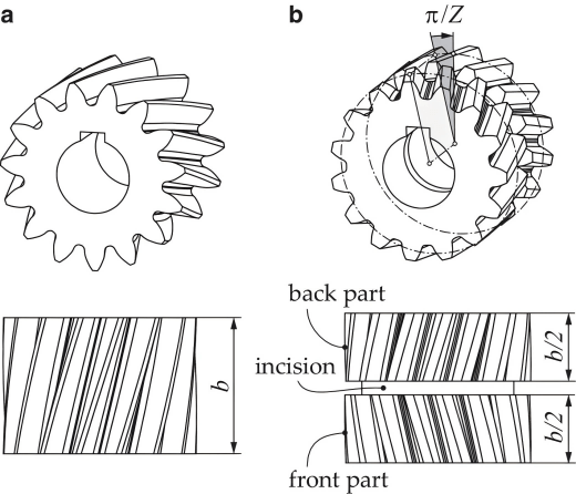
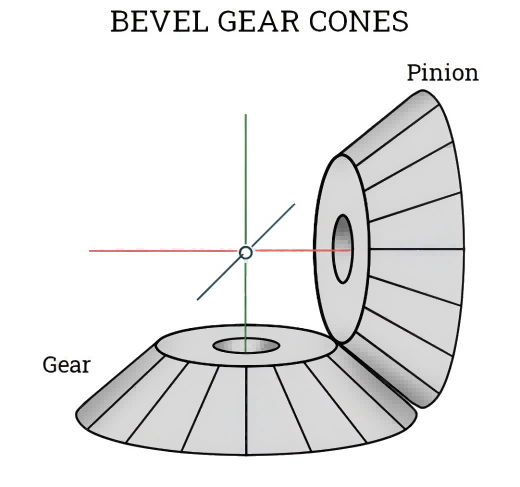
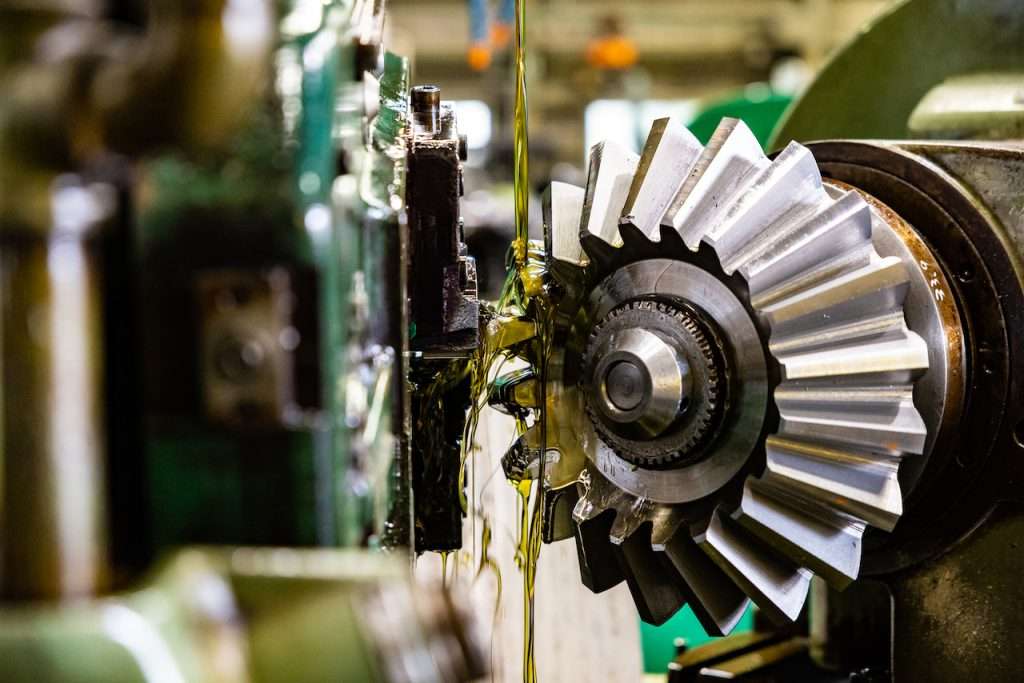
3. Bevel Gears
Gear Application:
Bevel Gear transmits motion from one shaft to another set of shafts placed at the right angle to each other.
Industries:
- Automotive Industry: Elements involved in differential systems that are used to rotate turnings at varying rates.
- Medical Device Industry: Used in surgical instruments and imaging systems because of their low noise precision motion.
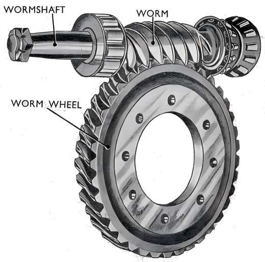
4. Worm Gears
Gear Application:
Worm Gear provides a high reduction ratio with high torque and a self-lock feature with compact dimensions.
Industries:
- Energy Industry:Applied to orientation systems of solar panels as well as Iterative position adjustment.
- Medical Device Industry: Used in dental chairs and in surgical robots where precise motion is required.
5. Rack and Pinion
Gear Application:
Use rotational motion to make accurate linear position movements.
Industries:
- Construction Industry: Used in elevators, lifts, and all other types of material handling equipment.
- Aerospace Industry: Found application in aircraft flight controls and landing mitre gear
The different gear types are tailored for the special needs of their gear application to run reliably and performant in various industries.
3.Gear material (Steel, aluminum alloys, and plastics)
The selection of appropriate gear material is essential to attaining the desired performance, reliability, and even specialty of the manufactured gears. A major requirement is that this material must be a metallic one and the three most widely used are steel, aluminum alloys, and plastics each for different purposes.
Steel (e.g., S45C Material)
- S45C materialis medium carbon steel and it is a commonly selected material requirement for gears because of its high tensile strength, high abrasion, and excellent toughness.
- It is preferred where tight accuracy is needed, and where it has high duties, particularly in clutch gears requiring intimate contact to pass on power.
- Raw Material Preparation:In steel gears, forging and heat treatment processes are performed to make it stronger like quenching and tempering to improve hardness.
Aluminum Alloys
- Durable and weighing less than steel, aluminum alloy contractors are widely sued where weight is a factor.
- Recommended for applications of medium loads and low inertia.
- Raw Material Preparation:These materials are produced by precision casting or by milling, occasionally heat treated to increase their toughness.
Plastics
- The popularity of plastic gears is attributed to low cost and noise, low-corrosive nature, and light load-carrying capacity.
- Common in consumer electronics, medical devices, and small machinery applications.
- Raw Material Preparation:Many qualities of injection molding guarantee the right dimensions and smooth surfaces so that they can function properly.
Manufacturers need to be familiar with the properties of each gear material to help design the geared elements in a way that meets a certain demand while at the same time being durable.
Raw Material Preparation-heat treatment
Raw Material Preparation is a very important process in the production of gears, they need to be prepared for the machining process and for the stresses that they are to be called upon to bear on the operation.
One such step is heat treatment by which one can improve the mechanical characteristics of gear materials such as steel, aluminum alloy, plastic, etc.
Purpose of Heat Treatment
- Enhances the degree of hardness, strength as well as the wearing capacity.
- Improves the material’s measures of performance in stress and fatigue.
- The internal stresses are also decreased to improve the dimensional stability of furniture.
Heat Treatment Techniques for Gears
- Annealing:Recoalescence eases pressing and machining, also it frees stress inside the material.
- Quenching and Tempering: Improves hardness or toughness by rapid cooling and heating or by placing the material in water and reheating it at a high temperature.
- Carburizing and Nitriding: Makes the surface very strong while making the core tough, important for the reduction of gear wear.
Application to Common Gear Materials
- Steel (e.g., S45C Material): May be quenched; tempered, or surfaced and made to bear the increased load and resist wear.
- Aluminum Alloys: These may be solution heat treated or aged to the required strength and corrosion-resistant levels.
- Plastics: While they may not be heat-treated conventionally, they could be stabilized by applications of the annealing process to lessen warping.
Impact on Gear Performance
- Raw Material Preparation therefore should involve proper heat treatment to have stronger and durable gears that can maintain the least backlash of gearsfor increased reliability in a wide range of applications.
Thus, using heat treatment in preparing gears prevents the development of imperfections that affect the efficiency of the end product and greatly improves the gear's strength and durability.
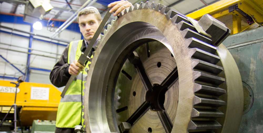
4.Rough Machining Gear Machining Gear cutting (Gear Milling Gear Grinding Gear hobbing) Gear chamfering
To finalize the physical properties of gear machining to a given standard of accuracy and performance, gear machining is broken down into several different production phases and employs a variety of different machining processes.
The end product is guaranteed to be accurate and robust, beginning with rough machining and continuing all the way up until the point where the gear cutting is perfect.
Rough Machining
- The first step involves the cutting of raw materials into the general geometrical configuration of the gears using a Computer Numeric Control cutting machine.
- Rough Machiningprocess that cuts away unwanted material as needed from the gear blank to make it ready for other fine operations such as the gear hobbing process or the milling of gears amongst others.
- It is performed subsequently to heat treatment to stabilize the material and thus enhance its machinability.
Gear Hobbing Process
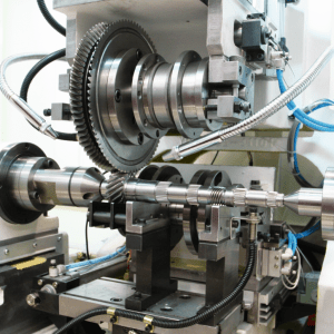
- On cutting gear teeth with a hob cutter, one of the most efficient of all processes is employed.
- Ideal for making spur, helical, and worm gear.
- Cut on precise CNC cutting machines to achieve a high level of precision and efficiency.
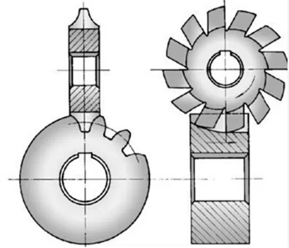
Gear Milling
- A versatile cutting tool is employed to shave gear teeth using various cuts that form the teeth outline.
- Probably be most effective if used in small lots or when designing new products in sportswear designs.
Gear Grinding
- The last of the finishing processes in gear manufacturing provides high accuracy of dimensions and smooth surface.
- Reduces errors that are brought in at earlier operations such as Roughing, or that may be in Gear Milling.
- Compared with plain bearings, it is indispensable for high-performance gears in severe working conditions.
Gear Chamfering
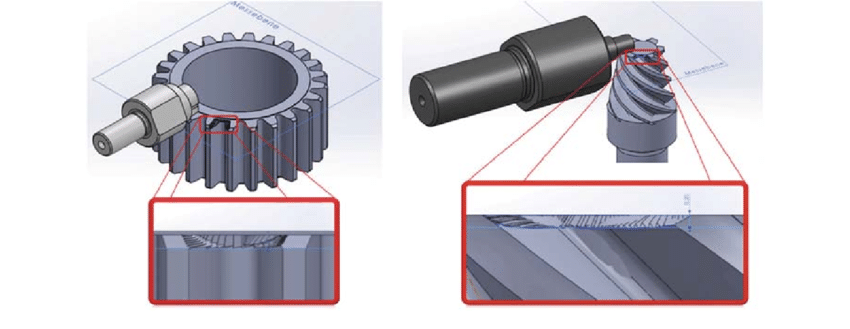
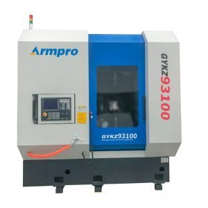
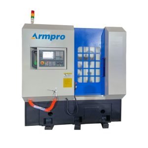
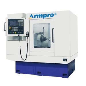
- Gear Chamfering Machine to remove a portion of the material that forms gear teeth, thereby, decreasing stress intensities and enhancing fitting.
- Can be incorporated into gear hobbing or gear milling as a single step frequently.
Precision in Every Stage
To manufacture high-quality gear broaching that is suitable for a variety of industries, they are regularly subjected to rough machining, which is a preliminary gear shaping process, followed by gear grinding, which is accomplished through improved and refined processes such as CNC cutting machines and heat treatment.
5. Why Gear Deburring is Becoming Increasingly Important in the Gear Manufacturing Process
The enhancement of the quality of the gears that are manufactured is a matter of great significance in today’s gear manufacturing business and this is because of the need to enhance the functionality and durability of the manufactured products.
The manufacturing process of gears also includes deburring and this is one of the important processes since gears when manufactured many times have sharp edges, burrs, and imperfections that need to be eliminated. This process has been receiving a lot of consideration because of the many applications in enhancing the functionality of gears, safety, and efficiency of the gears.
1. Extend the Lifespan of Gears:
The first advantage of gear deburring is related to the extended lifespan of gears. While deburring gets rid of any rough surface that can lead to more degeneration than is necessary, the gears can run for a longer time before such degradation sets in.
This is especially important in where gears are required to operate under high performance, for instance, automobile and aircraft manufacturing units. A gear chamfering machine becomes useful in deburring activities hence improving the durability of the gears.
2. Optimize Gear Performance:
Key to successful gear practice is gear chamfering which has been known to enhance the optimized performance of the gears. If the surface of the gears is not smooth that means that there will be certain areas of the teeth of the gear that do not engage fully with another gear; therefore, this decreases the efficiency of the gear system.
When these imperfections are stripped away, the gears are permitted to rotate with much more accuracy, which then minimizes the amount of friction that may be lost. This is because the design leads to enhanced efficiency of operation and increased power transmission which is important for optimum output across applications.
3. Reduce Friction Loss:
Friction loss is a commonly experienced issue in gear systems and takes a toll on energy efficiency and functionality. Somewhat rough and jagged edges on gears will raise the contact area of gear teeth, resulting in additional friction and, thus, heat.
Gear chamfering further assists in breaking these edges so that there are no issues of friction loss and gears run as they are supposed to run. Apart from energy conservation, it plays a major role in enhancing the efficiency of the system by lowering the friction levels.
4. Improve Gear Assembly Precision:
Increasing the gear assembly can be tough if the gears are not deburred correctly. Burrs can provide interference in the positioning of gear and during the fitting and hence, trigger the emergence of errors and create misalignments that lower the capability of the system.
When gears reach the gear tolerances accurately, gear chamfering adds up to the overall intentions of gear assembling. Enhancing such accuracy promotes higher levels of functionality and fitment of each gear within a system without compromising on reliability.
5. Improve Safety in the Workplace:
Improve safety in the workplace plays a vital role when it comes to combating high-risk factors within the workplace since any sharp edges are a potential risk factor to the employees when handling or assembling.
They use smooth surfaces in production to minimize contact injuries, which in turn, helps to have a safer employee population. Moreover, when gears are correctly deburred, their functional odds are low, and, therefore, possible accidents that may result from faulty gears are reduced.
Thus, the process of gear chamfering machine is quite essential in the manufacturing of gears and holds significant value as seen below points illustrating the various advantages that come with it such as improved gear performance, longer service life, and safety.
Moreover, tools like the gear chamfering machines applied on gears guarantee their quality and reliability in regards to their use as needed in different industries. Hence, by adopting better practices concerning friction loss, gear tolerances, and assembly precision among others, manufacturers can come up with superior products that also make the production process safer and more efficient.
6. Gear Inspection: A Critical Step in Gear Manufacturing
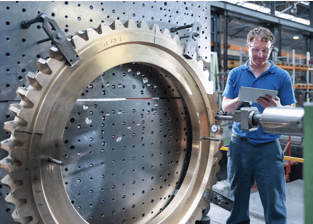
Gear inspection constitutes a vital step in the manufacturing process of gears to maintain standards of high-performing and durable gears. Adopting sophisticated methods and equipment enables manufacturing companies to provide for the quality, reliability, and safety of the products they produce.
Dimensional Measurement for Perfect Fit
The main feature is accurate dimensional measurement or geometrical accuracy as slight deviations can impair the performance of the gears, increase noise, or cause wear.
Role of Dimensional Measurement:
- Gauges ensure that gears are of the correct size and shape to fit into the required machinery.
- Eliminates conditions where the dimensions are off and this could lead to misalignment and many mechanical failures.
Use of Coordinate Measuring Machines (CMM):
- CMM offers accurate geometrical dimensions such as pitch circle diameter, module content, and the overall size of gears.
- It also provides nearly perfect inspection data as it eliminates the possibility of human error during the inspection process.
1. Hardness Testing for Durability
The strength of a gear describes its ability to withstand operating loads and wear and tear in terms of toughness, hardening, and fatigue. Correct hardness levels enable gears to be used in environments in which they are expected to operate.
Rockwell Hardness Test:
- The Rockwell Hardness Testis a well-defined procedure used to determine the hardness of the used gear materials.
The corresponding mechanical interactions measure the depth of penetration under a particular load, indicating dependable and reproducible performance characteristics.
Importance of Hardness Testing:
- Avoids excessive wear by making certain the material is hard enough to withstand wear and tear.
- Establishes that heat treatment processes such as carburizing or nitriding among others have been treated to develop surface strength.
2. Material Inspection via Chemical Composition Analysis
When it comes to gears, it is essential to keep in mind that these components must be fabricated from materials of a high standard to generate a consistent level of performance. It is the responsibility of the materials inspection to ensure that the base material chosen for manufacturing is up to the standard that has been established.
Chemical Composition Analysis:
- Chemical composition analysisconfirms that the gear material has the right composition as per the design of the gear.
- Identifies issues that affect a material’s mechanical characteristics and purity or those that are indicative of a change in mechanical characteristics.
Benefits of Material Inspection:
- Serves as a tool that helps ensure that material quality in different production batches will be of uniform quality.
- Improves robustness especially when it can’t afford to fail such as the medical devices manufacturing process.
3. Gear Profile Inspection for Precision Engagement
It is the geometry of the gear teeth chamfering machine that plays a significant role in the development of an efficient and effective power transmission system.
Greater frequency of contact is the result of any movement in the tooth thickness measurement, which eventually results in more friction and noise as well as decreased efficiency. This is because any deviation from the design target causes the gear profile to shift.
Gear Profile Inspection:
- Consists in analyzing the geometry of the contact surfaces of the interacting gears.
- Can identify non-circularity of tooth profile, the variation, or the spacing of the involute curve or pitch.
Advantages of Profile Inspection:
- Promotes the precise contact of the gear teeth thus making the operation quieter and efficient.
- Reduces wear through precise control of the tooth interaction profile.
4. Surface Roughness Inspection for Reduced Friction
Most gear applications have specific requirements as to the surface finish because it reduces friction, and improves lubrication, and gear durability.
Surface Roughness Measurement:
- It helps to measure the roughness of the gears and thus guarantees them a certain surface finish.
- Some sophisticated instruments by measuring characteristics such as Ra (arithmetic mean roughness) compare surface finish.
Importance of Surface Roughness Inspection:
- Enhances the ability to retain lubricant thus reducing the wear and energy loss accordingly.
- Improves the performance-duration characteristics in the gear pairs.
Gear inspection encompasses multiple critical processes, including Dimensional Measurement, Hardness Testing, gear profile inspection, and Surface Roughness inspection, all of which contribute to the quality and reliability of gears. Tools such as CMM and the Rockwell Hardness Test ensure that gears meet stringent standards, providing precision, durability, and efficiency.
By prioritizing gear inspection, manufacturers can produce high-performance gears that excel in demanding industries like aerospace, automotive, and energy.
Through meticulous inspection, the risks of gear failure, inefficiency, and operational downtime are significantly reduced, making it a cornerstone of modern gear manufacturing.
Conclusion
The future of gear manufacturing is being reshaped by innovations and emerging trends that enhance efficiency, precision, and sustainability. From advanced CNC machining and automation to eco-friendly materials and digital twins, these technologies are revolutionizing the industry.
As demands grow across sectors like automotive, aerospace, and energy, adopting these advancements will be key to staying competitive. By embracing these trends, manufacturers can deliver higher-quality gear while reducing costs and environmental impact, paving the way for a smarter, more sustainable future.
Don't forget to share this post!
Related Products
CONTACT US
Tell us your raw material and working details to get quotations within 24 hours.
WhatsApp Us: +86 159 27 555863

Want the best price & newest metal working machinery buying guide,tips and trends sent straightly to your box?Sign up for Armpro's monthly newsletter,we're free for your consultation and Offer you the most suitable working solutions!
The Buyer's Guide
- Tapping Machine: The Ultimate Buying Guide in 2024
- Electric Tapping Machines:the Ultimate Buying Guide in 2024
- Drilling Machine: The Ultimate Buying Guide in 2024
- Drilling milling Machine:The Ultimate Buying Guide in 2024
- CNC Tapping Machine :The Complete Buying Guide in 2024
- Pipe chafering Machine:The Complete Importing Guide in 2024
- Radial drilling Machine:The Complete Buying Guide in 2024
- Thread rolling Machine:The Complete Buying Guide In 2024
- Pillar Drilling Machine:The Ultimate Buying Guide in 2024
